Posts
Generating synthetic stereo reconstruction datasets with Blender
Daniel HübnerPosted on May 29, 2024
Introduction
Stereo reconstruction is the process of creating a three-dimensional digital twin of an object using only captured images of that object. We usually distinguish between monocular, binocular and multi-view stereo reconstruction. The first one uses a single image and analyzes texture, shadows, perspective etc. to gain information about depth. The second method, binocular 3D reconstruction, uses exactly two images and obtains depth information from the offset of features in both images. Finally, multi-view stereo reconstruction is based on at least three images. If we are using more than one image, those can be taken either at different points in time or in space. In this post, my focus is on binocular stereo reconstruction, with the two images taken at different locations in space.
Stereo reconstruction is one of the most researched problems in computer vision and there exists a vast amount of algorithms to solve this challenge. The state of the art is based on neural networks, but there are also a lot of traditional algorithms. There are two well-known benchmark datasets for training, testing and ranking different reconstruction algorithms, which can be found on the homepages of Middlebury and KITTI.
Finding the best camera settings to obtain good reconstruction results requires to capture many images of an object. This can be a very time consuming process. In my case, I was in particular interested in different distances between the two optical axes of a binocular stereo camera. However, changing the relative position of the two cameras required recalibration.
Additionally, I had a whole bunch of different reconstruction algorithms implemented and wanted to evaluate and compare their performance in various lighting setups. This required capturing of a lot of images, and again some changes to the scene involved recalibration.
Hence I decided to model a digital twin of my whole setup in Blender 4.0 in order to generate a synthetic dataset of the scene with slightly varying parameters. These images then could be used to evaluate how my stereo reconstruction algorithms performed in different setups. Blender is a powerful, free and open-source computer graphics application, which can, inter alia, render photorealistic images of a scene.
Additionally, I wanted to examine active stereo, where a dot pattern is projected into the setup to generate features on textureless regions. Thankfully, this can also be easily modelled in Blender.
In this post, I will explain, how I reproduced my scene in Blender, rendered photorealistic images taken by a binocular stereo camera and added a pattern projector for active stereo reconstruction. I won’t go into Blender details and recommend to check out BLender’s reference manual and tutorials on YouTube.
Learning blender from scratch is not easy and I am far from being an expert. If you know a better way to achieve any of the following steps, please let me know in the comments.
Build a scene
The first thing, which I had to do, was to build a scene. Whatever object I wanted to capture in the real world had to get its digital twin and had to be modelled in Blender. For this, I created a new, general project and removed the predefined cube, light source and camera. Afterwards I added my desired objects and light sources. I also added a plane as ground to my scene, as I wanted a realistic setting.
There are multiple repositories out there, where one can get ready-to-use models from, some assets are even free of charge. Have a look at blenderkit, free3d, cgtrader or TurboSquid, for example. I want to preempt here, that textured surfaces are needed for the stereo reconstruction (I will explain in the next section why). For this reason I preferrably searched for models, which are shipped with prebuilt textures.
You can also sculpt your own models, but I will not go into details on how to do that. There are some really good tutorials for this topic, e. g. on YouTube.
Add textures
Binocular stereo reconstruction works by finding matches between two images. Given a feature (single pixel, window of pixels or an object) in one of the images, we search for this feature in the other image. The offset in the locations within the image coordinate systems will yield us the depth information. When looking for matches, textureless regions lead to ambiguity, as a desired feature might be detected at multiple locations (think of finding the location of a white pixel on a white wall). Hence, I had to add textures to my objects and for the same reason avoid repeating patterns within these textures.
Luckily there are models with predefined textures at the aforementioned repositories.
Nevertheless, I had to add my own textures e. g. for the ground.
In my case, I took images in my flat of the floor, blankets, curtains and sofa fabrics and added them as materials to Blender.
I recommend again to watch some YouTube tutorials on how to add textures, as there are multiple ways to do this.
As I only wanted to add textures to very simple objects (e. g. the ground), I opted for the simplest approach I found.
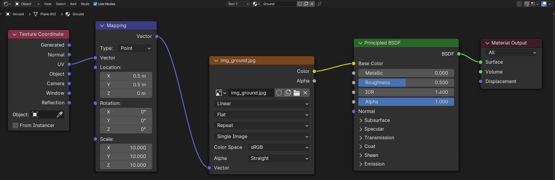
I selected one of my fabric images as Base Color for each object in the Material category of the Properties editor and rescaled/tiled the textures in the UV Editing workspace.
Afterwards, I shifted the relative position of my texture using a Texture Coordinate and a Mapping node in the Shader Editor (Shading workspace), as can be seen in the example below.
Configure the stereo camera
Blender has internal settings for stereo cameras (I think, it is a feature since about version 2.7) and we do not have to create individual left and right cameras anymore. For an overview please refer also to the stereoscopy section in Blender’s reference manual.
First, I had to add a camera to the scene and move and rotate it into the desired position in the 3D viewport (Layout workspace). Note in this context, that you can check the camera perspective using the default hotkey Numpad0. If you want to keep the camera centered on a specific object, while you move it around in your scene, you could additionally add a “Damped Track” constraint for the -Z axis.
To enable stereoscopic rendering, Stereoscopy in the Output category of the Properties editor has to be checked.
I chose Stereo 3D for the output mode and enabled both the left and right image.
After selecting the camera in the Outliner, I went to the Data category on the Properties editor.
There, I chose “Perspective” for the lens’ Type and set my desired Focal Length and sensor size to fit my real world camera.
Note, that there is also some presets for the latter setting.
Now to the interesting part, the stereoscopy section. There are three different modes (see also Stereo 3D Camera in Blender’s reference manual):
- Off-Axis: This shifts the frustum/cone of the cameras, such that their optical axes converge at a given distance, and represents human vision best.
- Parallel: This generates two parallel cameras without convergence of their optical axes.
- Toe-in: This rotates the cameras instead of shifting their frustums.
Of special importance is the Interocular Distance, which defines the distance between the two optical axes of the cameras.
A small distance will yield better reconstruction results, but in the real world setting, there might be limitations on the minimal distance between both cameras.
I set “Center” as Pivot, which placed my stereo camera centered at the position, which can be seen in the scene in the 3D Layout.
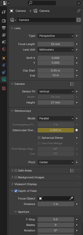
To model my real world camera better, I also added a Depth of Field.
My chosen camera settings can be seen in the image below.
You might be wondering, why Interocular Distance is marked yellow in my case.
This is because I have animated this property and rendered images with different distances between the left and right camera.
Store depth map
In some cases it can make sense to obtain the ground truth depth map for the scene.
Blender is able to directly output an image for each camera lens, which contains the depth information with respect to the lens’ position relative to the scene.
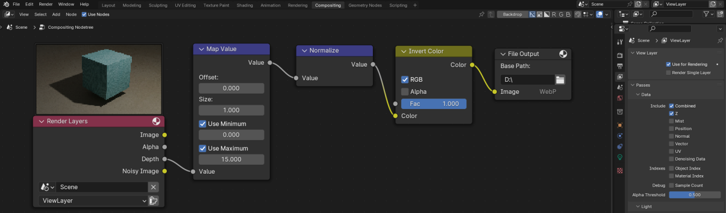
For this, I first activated depth rendering in the View Layer category on the Properties editor by checking the Z box of the Include property on the “Passes” panel in the “Data” section.
For the next step to work, I also checked that the Compositing Pipeline was activated in the Output properties on the “Post Processing” panel.
Then I opened the Compositor (Compositing workspace) and added one node of Map Value, Normalize, Invert Color and File Output each.
I connected the nodes like shown in the image below.
It was quite challenging to find good values for the Map Value node, as poor values resulted in an image with low contrast.
I found it also difficult to match the colors of the final images somehow with the depth maps, which I had obtained from stereo reconstruction algorithms.
The depth maps for the left and right lens are shown below. Note, that I cropped the depth at a maximal value in the
Map Value node, which leads to the black background in the images.
|

|
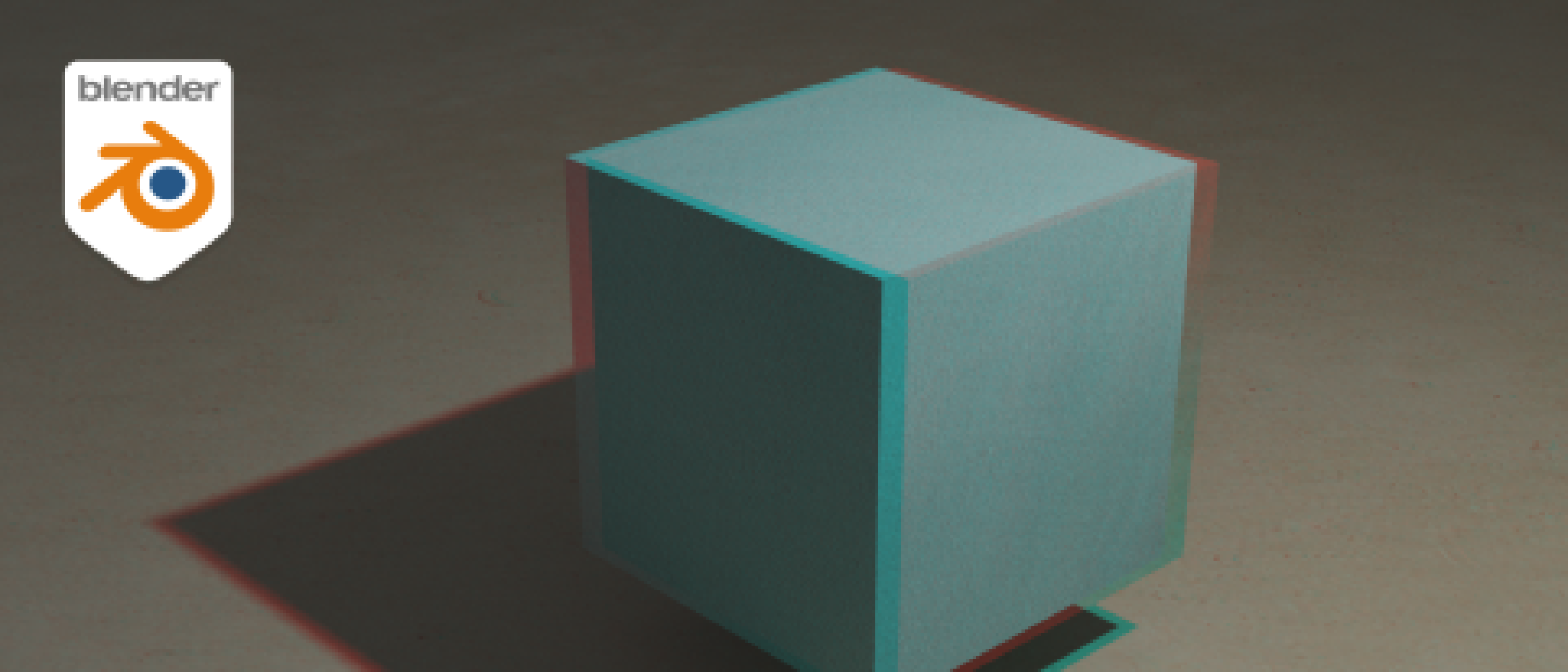
Render images
For the final step to obtain stereo images the scene has to be rendered.
To do so, I chose the “Cycles” engine in the Render properties and activated rendering on my GPU.
I also checked Denoise in the “Render” section of the “Sampling” panel to avoid numerical artifacts in my images.
I did not touch any other settings and left them at their default values.
Back at the Output properties, I set my desired image resolution, output folder and file format.
As I wanted to receive two images, which serve as input for the stereo reconstruction algorithms, I chose “Individual” for the Views Format.
Finally, I rendered the images.
|
|
Obtain camera intrinsics and extrinsics
For most stereo reconstruction algorithms the images have to be undistorted and rectified, i. e. projected onto a common image plane. To remove lens distortion we need the camera’s intrinsic and for rectification the extrinsic parameters. To learn more about camera calibration, I recommend the book Learning OpenCV1 by Bradski, G. and Kaehler, A. The authors explain the camera model and calibration algorithms in detail from a mathematical point of view. They also provide some code examples (in C++) on how to use the openCV module for the task.
Blender supports scripting in python and provides us with a Scripting workspace for this. One can find the code to extract the intrinsic and extrinsic camera parameters on the web. For the sake of completeness you can find my script here.
Add noise for more realistic images
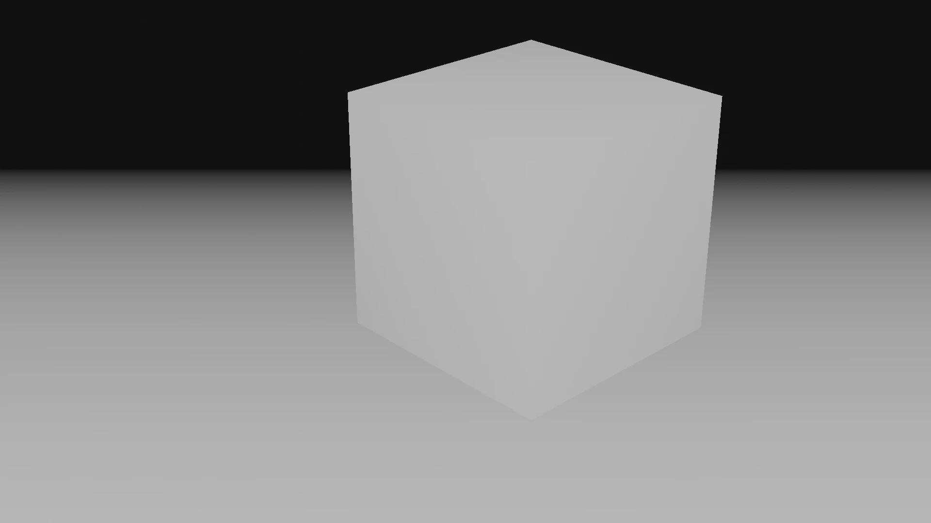
You might notice, that the rendered images are kind of idealistic and differ from real world captures.
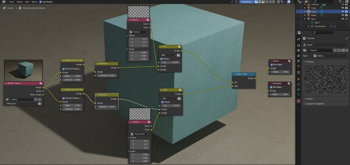
To get more realistic results, I modified the left and right images individually using the Compositor (this is possible, if the “Compositing” Pipeline is active on the “Post Processing” panel of the Output properties).
Use nodes at the top of the Compositor has to be checked.
I split the Image output of the Render Layers node and applied a Brightness/Contrast and an Exposure node to each of the images with slightly different parameters.
I compared the obtained images to my real world images and adjusted the values of the compositing nodes to get a good match.
To add noise to the images, I created two Texture nodes and added two different textures of Type “Noise” to them.
I then combined the noise with the image by putting both into a Mix node with mode “Add”.
Finally, the two images get combined back together via a Switch View node and then into the output nodes Viewer and Composite.
The Viewer node is what is shown in the node editor background (if you have activated “Backdrop” in the upper right corner), and the Composite node is what is seen in the final render.
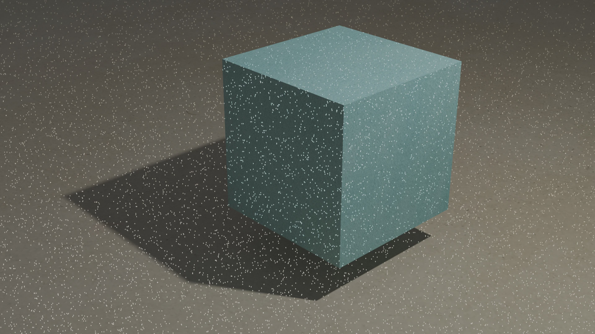
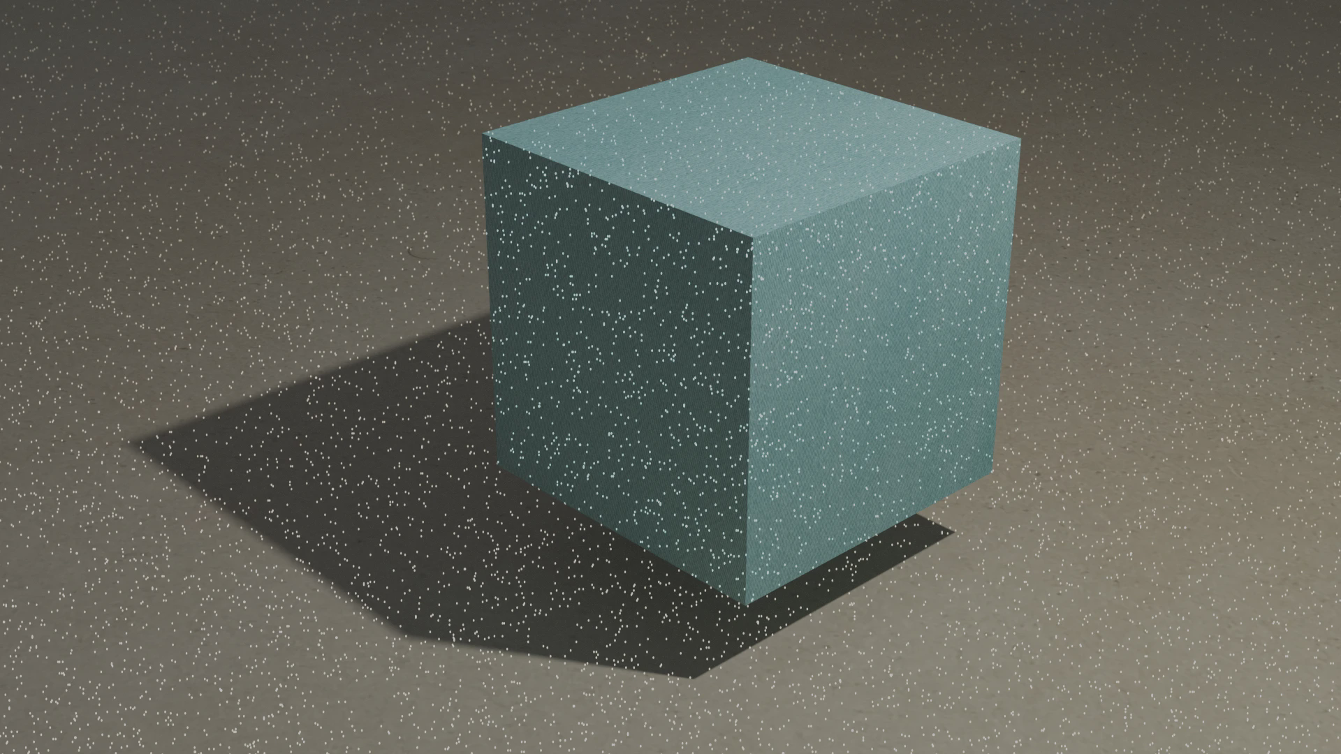
Add a pattern projector for active stereo
As I mentioned above, textureless regions can lead to ambiguity in stereo reconstruction. It is hard to exactly locate a matching feature on a plain region. Active stereo2 circumvents this issue by projecting a pattern (e. g. random dots) onto the scene, which creates features in textureless regions. This can also be achieved in Blender.
Generate pattern image
First, one has to create an image with the desired pattern. The pattern will be projected into the Blender scene, while the (transparent) background of the image will not be seen. One could plot this pattern image by hand in any drawing application or generate it by coding. I opted for a simple python script, which plots white pixel at random locations onto a black background and stores the image with a transparent background. You can find it here.
Add projector to Blender scene
Next, I had to add a pattern projector to my scene.
For this, I added an additional light source of type Spot.
I checked that Cast Shadow and Multiple Importance were activated, to not only enable shadows for the projector, but also reduce noise in my projected pattern.
In the “Beam Shape” section I set Blend to 0.0, such that I had sharp edges.
This mimicked my real world projector.
In the “Nodes” panel, I set the Surface value to Emission, the Color to “Image Texture” and chose my generated pattern image as source.
Using the “Preview” panel at the top of the category, I adjusted the Power value, such that the pattern was clearly visible.
Attach projector to camera
In my real world setting, the pattern projector will be attached to the stereo camera and I wanted to reflect this in Blender.
Hence I added two constraints Copy Location and Copy Rotation to the projector, both with the stereo camera as Target and active on all three axes.
|
|
Adjust IOR of textures
To obtain results close to reality, the index of refraction (IOR) (also called refractive index) of the used materials is important. While human skin has an IOR of about 1.4, glass has about 1.6 and iron has even an IOR of almost 3.
I searched typical values for the materials I used in my scene and adjusted the parameters for all textures in my Principled BSDF nodes in the Shader Editor.
Final remarks
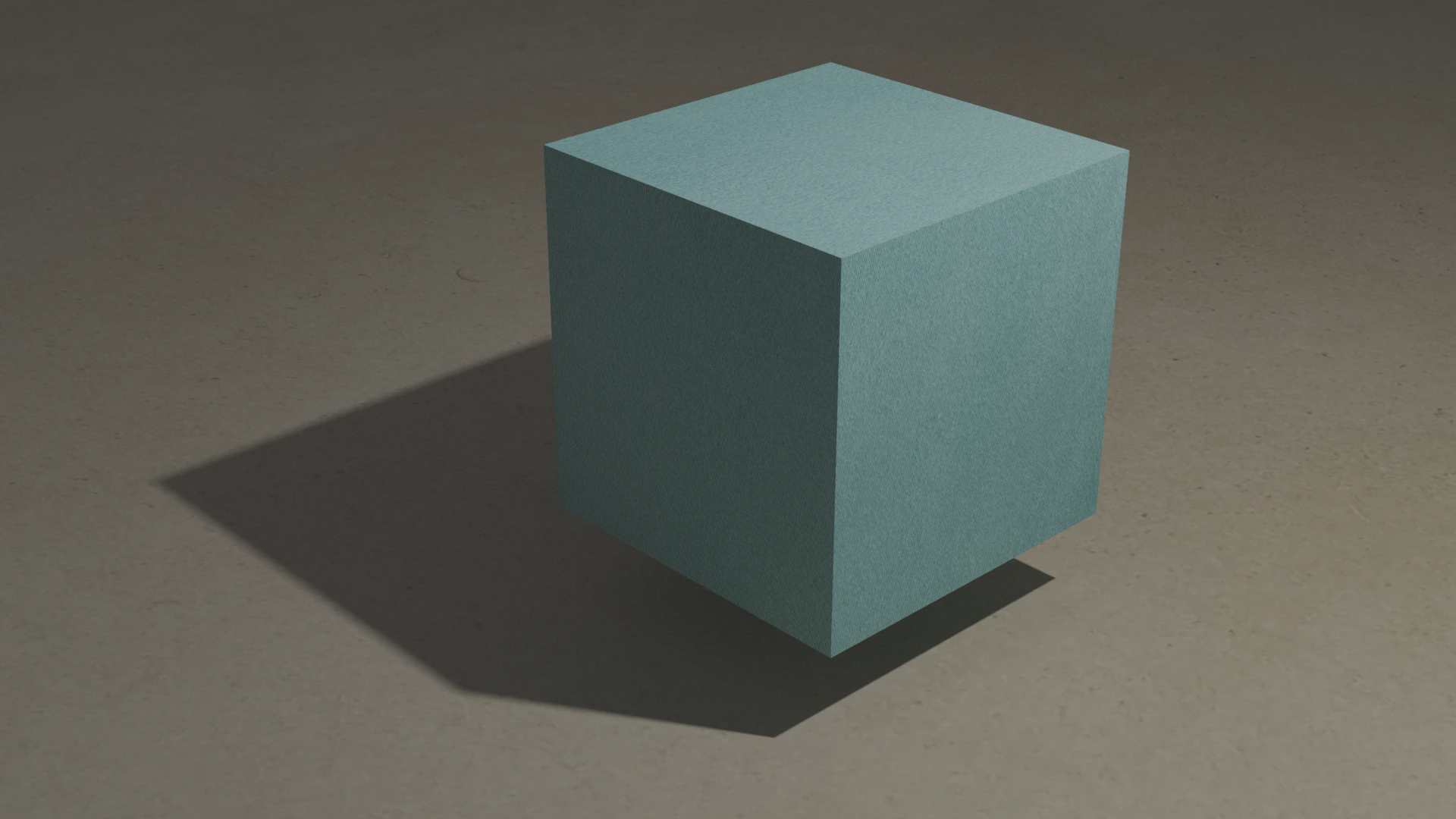
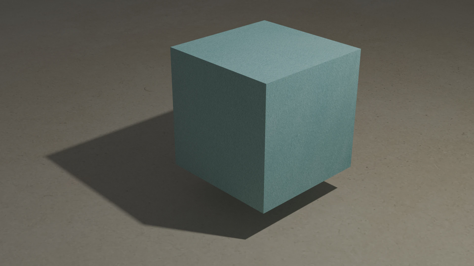
The final images looked very close to my real world ones.
However, when I ran the images through my stereo reconstruction pipelines, the real world images produced worse results than the synthetic inputs generated by Blender.
Further investigation showed different focus distances of my two cameras, which might be the reason for a lot of false matches during the reconstruction step.
I have not yet found a way to directly simulate this in Blender.
One could simply add a Gaussian Blur filter in the Compositor, but I guess the better option is to render twice with different values for the Depth of Field.
For me as a Blender beginner, it has been challenging to find good explanations on how to perform each of the above steps. This was due to the fact, that often there were multiple ways to achieve my goal.
Nevertheless, I am quite satisfied with the obtained results. In my opinion it was worth the effort of about two work days to create the scene in Blender, as the digital twin of my setup saves me a lot of time. Now I am able to experiment with different settings and investigate, if and how other hardware could improve my results.